News & Events
Revit Visibility Graphics Hierarchy Explained: What Overrides What
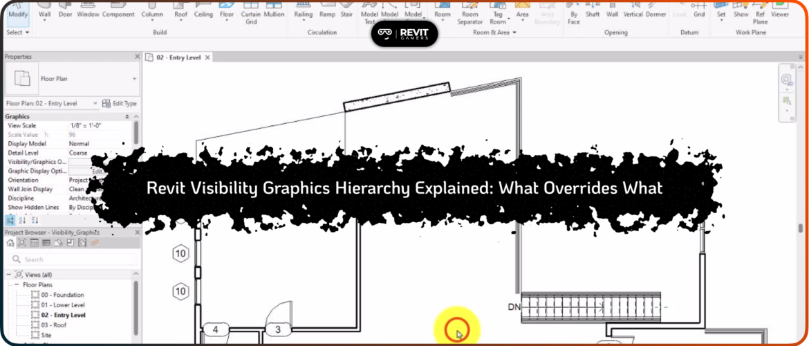
Visibility problems in Revit often confuse users because a single element may appear in one view but remain invisible in another. Unlike simple mistakes, these issues usually result from misunderstanding the Revit visibility graphics hierarchy, which governs how different settings interact to display elements. The hierarchy determines whether an element is visible, partially visible, or hidden in a specific view, and why its graphics may differ across elevations or plans.
Common visibility problems include missing walls, floors, roofs, or annotations in a view. Sometimes, elements are temporarily hidden, filtered, or assigned to a phase that isn’t displayed. Users often waste time toggling random settings without understanding the chain of control, which leads to frustration and inefficiency.
Recognizing that visibility is controlled by multiple layers—from global Object Styles and Materials to view-specific overrides, filters, and linework tools—is essential for solving these problems. By approaching visibility systematically, starting at the top of the hierarchy and working downward, users can locate the root cause of any issue quickly. This structured approach prevents trial-and-error fixes, ensures consistency, and maintains clean, professional model views.
Learn more: Revit Course for Beginners: Step-by-Step Animated Guide
Understanding the Concept of Visibility & Graphics Hierarchy
The visibility graphics hierarchy in Revit is a structured order of control settings determining how an element appears in each view. At its core, Revit prioritizes lower levels over upper levels: any setting lower in the hierarchy overrides the ones above it. Understanding this concept is critical for troubleshooting hidden elements or inconsistent graphics.
At the top are global settings, such as Object Styles and Materials, which affect the entire model. Moving down, view-specific controls like Visibility/Graphics Overrides, Phase Filters, and Element Overrides offer finer control. At the bottom lies the Linework tool, which overrides all other settings when applied.
Problems arise when users are unaware of this sequence. For instance, changing Object Styles may not make an element visible if a Filter or Element Override hides it. Similarly, a phase filter can make a new wall invisible even if all categories are turned on.
A structured approach—checking settings from the top of the hierarchy and moving downward—is the most efficient way to diagnose visibility issues. By understanding each level’s influence, users can systematically isolate the cause of a hidden element, maintain consistent graphics across views, and avoid accidental overrides that create more problems.
Object Styles: The Top-Level Global Control
Object Styles are the highest level in the Revit visibility graphics hierarchy, controlling the graphical appearance of element categories across the entire model. They manage line weights, colors, patterns, and materials globally. Adjusting these settings affects all views unless overridden by lower levels, making Object Styles a powerful but sometimes overlooked source of visibility issues.
Problems often occur when users expect a change in a single view to affect everything or assume elements are hidden due to view-specific controls. For example, a wall may appear faint or invisible if its category line weight is set too low or if subcategory overrides are misconfigured in Object Styles.
To address these issues, open the Manage tab → Object Styles, and verify category and subcategory settings. Ensure line weights, colors, and visibility settings are appropriate for all model scales. Avoid making changes directly in view overrides if the intention is a global fix.
Using Object Styles correctly ensures consistent model presentation, reduces unnecessary overrides, and prevents confusion when elements appear hidden in multiple views. Global adjustments here save time and form the foundation for troubleshooting lower-level visibility issues effectively.
Materials: Global Overrides That Can Change Everything
Materials in Revit provide a global override for the appearance of elements, controlling textures, colors, and render graphics. When a material is assigned at the Type or Instance level, it can override Object Styles, making elements appear differently across all views. Misapplied materials are a common reason walls, floors, or roofs look inconsistent or even invisible.
For instance, a material with a transparent or non-rendered appearance may cause a wall to seem hidden in shaded or realistic views, even if its category is visible. Similarly, mismatched Type or Instance materials can create unexpected graphics conflicts when multiple team members adjust elements independently.
To solve material-related visibility issues, inspect the element properties. Verify that assigned materials are intentional, consistent, and not set to fully transparent. Use Material Browser to confirm appearances and adjust as necessary. Keep Type-level materials uniform to reduce accidental overrides.
Materials are global, so correcting them ensures uniformity across all views. Understanding their position in the hierarchy allows users to anticipate how changes propagate, prevent conflicting overrides, and maintain professional, predictable graphics throughout the project.
Learn more: Revit vs AutoCAD 2025: Which Is Worth Learning?
Visibility & Graphics Overrides (VG): View-Specific Control
Visibility & Graphics Overrides (VG) are view-specific settings that allow users to control categories, subcategories, and elements within a single view, overriding global Object Styles and Materials. These overrides are crucial for creating customized views, such as presentation plans or construction documents, but can also hide elements unintentionally.
Common issues include elements disappearing in a view despite being visible globally. For example, turning off the “Walls” category in VG for a floor plan may make walls invisible while they remain visible in other views. Misconfigured Subcategory Overrides, Detail Level mismatches, or toggled annotation visibility can also trigger confusion.
To resolve these problems, access View Properties → Visibility/Graphics (VG). Ensure that required categories are checked, subcategory overrides match expectations, and view filters are considered. Use “Reveal Hidden Elements” to identify temporarily hidden objects.
Proper use of VG allows precise control over each view without affecting the global model. Understanding its position in the hierarchy ensures predictable graphics, prevents accidental element disappearance, and maintains clarity in documentation.
Phases & Phase Filters: The Silent Visibility Killers
Phases and Phase Filters control visibility based on project stages, such as existing, demolished, or new construction. Although crucial for renovation and phased projects, they are frequent causes of hidden elements. A wall or floor might vanish in a view simply because the phase filter does not include it.
Problems occur when teams overlook phase assignments or use inconsistent filters across views. For example, a “New Construction” wall will remain invisible in a view set to display “Existing” elements only. This often confuses new users, who may mistakenly toggle categories or VG settings instead of checking phases.
To fix phase-related visibility issues, open View Properties → Phase → Phase Filter. Confirm that elements belong to the correct phase and that the active filter includes those phases. Consistency across views is critical; use project standards to avoid misalignment.
Proper management of phases prevents invisible elements, ensures correct documentation, and allows phased construction to be accurately represented in both 2D and 3D views. Understanding that phase filters override VG and Object Styles in specific contexts is key.
Filters: Powerful, Dangerous, and Often Misused
Filters in Revit allow users to override graphics for elements meeting specific criteria, such as category, parameter value, or phase. Positioned below VG but above Element Overrides in the hierarchy, filters can make elements invisible or dramatically change their appearance if misapplied.
A common mistake is applying a filter that unintentionally hides important elements. For example, a filter set to hide “Furniture” elements in a renovation view may also hide other elements due to misconfigured rules. Filters also override Object Styles and VG for affected elements, making them a frequent culprit in hidden or inconsistent graphics.
To resolve filter-related issues, review View → Visibility/Graphics → Filters. Check which rules apply and adjust criteria carefully. Test changes in multiple views to ensure filters do not unintentionally hide essential components.
Using filters properly allows for complex, condition-based graphics control while maintaining consistency. Mismanagement, however, can create invisible elements or unpredictable graphics, emphasizing the importance of understanding their hierarchical position.
Element Overrides & Hide/Override Graphics in View
Element Overrides in Revit allow users to directly control the graphical appearance of individual elements within a specific view. This feature overrides category settings, filters, and even Visibility/Graphics (VG) settings for that particular element, providing precise control over color, line weight, patterns, and transparency. Misunderstanding or misapplying these overrides is a frequent cause of elements appearing differently or “hidden” in a view, even when their category is visible.
To manage Element Overrides, open View → Visibility/Graphics → Overrides or select the element and use the Override Graphics in View dialog. Here, you can adjust line styles, colors, and surface patterns as needed. If an element seems missing or visually inconsistent, check for applied overrides first, as they take precedence over filters and VG settings in that view.
Proper use of Element Overrides ensures elements are highlighted, differentiated, or customized for documentation purposes without affecting other views. By combining careful overrides with an understanding of the hierarchy, users can maintain consistent and professional graphics, control presentation quality, and avoid visual conflicts in collaborative projects.
Learn more: Revit Classes Comparison: In-Person vs Online with Visuals
Linework Tool: The Strongest Override (Use with Caution)
The Linework tool sits at the bottom of the hierarchy, overriding all other settings, including Object Styles, Materials, VG, Filters, and Element Overrides. It allows users to change line styles, join edges, or emphasize geometry, making it extremely powerful.
However, misuse can create inconsistencies. For example, changing line styles in one view without standardization can cause elements to appear differently in other views, confusing team members. To avoid problems, use Linework selectively and document any changes.
Professional workflows recommend starting from the top of the hierarchy and only using the Linework tool when other overrides do not achieve the desired result. Understanding its power ensures precise control, maintains graphics consistency, and prevents accidental hidden or misrepresented elements in the model.
Leave a Reply
You must be logged in to post a comment.